Что-то не так?
Пожалуйста, отключите Adblock.
Портал QRZ.RU существует только за счет рекламы, поэтому мы были бы Вам благодарны если Вы внесете сайт в список исключений. Мы стараемся размещать только релевантную рекламу, которая будет интересна не только рекламодателям, но и нашим читателям. Отключив Adblock, вы поможете не только нам, но и себе. Спасибо.
Как добавить наш сайт в исключения AdBlockРеклама
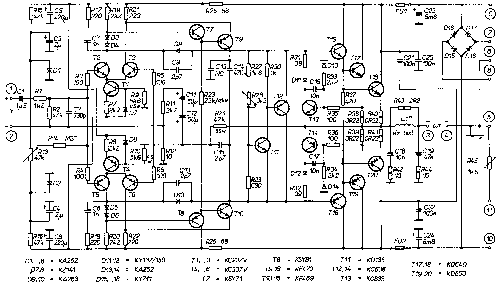
The DPA 220 schematic

The DPA 220 low detail schematic (click on the image to see
the high detailed version (47 Kb)
Do not try to print this picture in Netscape because it's too big.
T1 to T6 create the input differential stage. The D7
and D8 zener diodes stabilize at 5V. These are just the simplest low-power
zeners, only they have to be coupled in tolerance of 200 milivolts, which should
not be a problem. T1 to T6 are common all-purpose low-power transistors with
high Hfe. These six and maybe the next four have to be coupled in tolerance of
25%.
The T7 and T8 are fast, switching application types.
T9 and T10 have to be fast and must hold a high voltage, thus the best are the
"video" types - BF469/470. T15 and T16 are the same types.
The C9, C10 and C15 should stand voltages higher than usual 50 V - I don't know
why.
D3 to D6 can be any silicon type, not Scottky, the ones listed below are just
all-purpose low-current ones for 150 V. These diodes should be rather fast -
"switching types".
The T11 and T12 stabilize the BIAS current for the power stage. T11 also
serves as a temperature sensor, and is mounted to the cooler of power
transistors.
T13 and T14 secure the output current - in cooperation with R38 and R39.
The output transistors used here are Tesla types - Tesla is a former
local devices manufacturer - the pair in each branch can be replaced with a
single power darlington, like BD649/BD650. They should have Pc > 150W, Ic > 15A,
Uceo > 100V.
In this case obviously the R38+R40 / R39+R41 must be connected parallel. These
resistors should be able to absorb high power - at least 2 W, but I'd use 5W
ones.
The output filter improves stability of the amp when working with complex
impedance of speakers - it is quite important. The resistors are high-power ones
again, the coil is 13 turns of a 1.2 mm wire on a 8 mm thorn (diameter). R43 is
placed coaxially in the coil.
The schematic also includes power supply capacitors and rectifier - the
capacitors' size is not crucial, generally the bigger the better. The rectifier
originally consists of four silicon 10A diodes, but you can use whatever you
have - rectifier bridge etc. The trafo should be a 2 * 30 V / 7 A type so that
you have +/- 40 V on the power supply capacitors.
In the scheme there's also a thermistor that is supposed to be connected to some
additional circuits that secure temperature and other things.
The complementary input stage of DPA amps is an unmistakable heir of earlier designs published by Mr. Borbely in several issues of Volume 1984 of the Audio Amateur.